Home
Welcome to the TunaTinS wiki!
This code is used with the Tuna Tin S, a low power amateur radio radiotelegraphy (CW) transmitter designed by Bob Fontana, AK3Y. The full circuit description and construction details are published in December 2020 QST Journal with an update in the September 2022 issue https://www.arrl.org/qst .
The original Arduino sketch code set up the Si5351 module for operation within one frequency band. An encoder switch allowed selection of frequency and tuning steps within that one band. The author's original Arduino sketch codes are accessible to ARRL members in the https://www.arrl.org/qst-in-depth archive. The Arduino IDE originally required installation of the Adafruit SSD1306 (Adafruit_SSD1306.h) and the Adafruit Si5351 (Adafruit_SI5351.h) Libraries to compile this sketch.
Our updated version 2.3.1 Arduino Nano sketch described below is based on Fontana's original code with the enhancements enumerated below.
The Arduino IDE requires installation of the Adafruit SSD_1306 library and NT7S's Etherkit Si5351 library from its Library Manager to compile the sketch. The Upload Procedure for the libraries and sketch is posted in the Wiki
Version 2.3.1 – for Arduino Nano with SSD1306 128x64 OLED Display and Integrated 10 MHz Frequency Calibration and Keyer
Original design: Bob Fontana AK3Y Optimizations & revisions: Carol Milazzo KP4MD
The Tuna Tin S v2.3.1 is a compact, Arduino-based low power telegraphy transmitter with:
- Si5351 frequency synthesizer
- OLED display (128×64, SSD1306)
- EC11 (KY-040) Rotary encoder with push-button
- SPDT slide switch input activates a DPDT relay for transmit mode, (one relay pole pulls up the Arduino Nano D8 pin to mute the Si5351 during receive, the other relay pole switches the antenna between the transmitter and an external receiver). See our Project Schematic Diagram.
- In addition to controlling the Tuna Tin S transmitter frequencies, the software allows the Si5351 to serve as a low-level signal source (Variable Frequency Oscillator) continuously variable from 4 kHz through 225 MHz.
- The software incorporates a calibration function that can set the frequency accuracy to 0.1 ppm over the entire 4 kHz to 225 MHz frequency range. The calibration factor is stored in non-volatile EEPROM memory. The procedure requires a receiver tuned to WWV or another accurate 10 MHz frequency standard, or an accurate frequency counter or spectrum analyzer.
- Each of the 15 amateur radio frequency bands from 2200m (137 kHz) through 1.25m (222 MHz) is preset to its QRP CW calling frequency upon power up.
- Each frequency band retains its last used frequency in memory while powered up.
- The user may define and store a default startup frequency in non-volatile EEPROM memory.
- The EEPROM memory retains the stored data even when the power is off.
- Straight key or iambic keyer adjustable from 8 wpm to 40 wpm.
This guide explains how to operate the device, use the encoder, adjust frequency and step size, and save settings.
- NT7S’s Etherkit Si5351 library automates the PLL setup and offers continuous RF spectrum coverage from 4 kHz through 225 MHz.
- The encoder serves multiple functions. Rotation adjusts a frequency digit or step size. One quick tap (<0.5s) alternates the encoder between digit select and digit adjust modes. A medium press (0.5-1.5s) toggles between straight key and iambic keyer modes. Press, hold and rotate → adjusts Keyer speed (only in Iambic Keyer Mode). A long press (1.5-3s) toggles between normal operating mode and calibration mode. A long press (>3s) saves the displayed frequency as a user-defined startup frequency (in normal mode) or saves the displayed ppb crystal correction factor (in calibration node) into non-volatile EEPROM.
- The tuning steps are: Band change, 1 MHz, 100 kHz, 10 kHz, 1 kHz, 100 Hz, 10 Hz and 1 Hz, in either direction. The 60m band tuning steps through the USA's five discrete 5 MHz channels.
- The integrated frequency calibration function permits setting the crystal correction factor to 0.1 ppm and saves it into non-volatile EEPROM.
- Rotate: changes frequency or selects digits, depending on the encoder mode
- Press: toggles modes or saves values
- When LOW, enables Si5351 output (Transmit) and switches the antenna relay to the transmitter.
- When HIGH, disables output (Receive) and switches the antenna relay to an external receiver.
The OLED display shows:
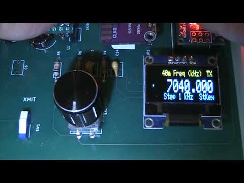
- Top Line shows Band Name (in Normal Operating Mode) or Calibrate XXXX ppb (in Calibration Mode), and "RX" in receive mode or "TX" in transmit mode.
- Encoder Position Dot indicates which display line is active: the Frequency or the Step Size.
- Frequency in kHz (large text)
- Bottom Line shows the Step Size or 60m Channel, and "StKey" in Straight Key mode or "XXwpm" in Iambic Keyer mode.
- Adafruit SSD_1306
- Etherkit Si5351
- Rotating the encoder changes the frequency by the current step size
- Tap the encoder button once quickly to toggle between digit adjust and digit select modes
- Rotate the encoder to select the active digit / step size for fine adjustments. The Step size appears in the bottom display line and as an underline cursor under the digit being tuned.
A medium press (0.5 - 1.5 s) on the encoder button toggles the keyer mode between Straight Key and Iambic Keyer. The Keyer Mode indicator in the lower right hand corner of the OLED display will read "StKey" for Straight Key or "XXwpm", showing the speed setting of the iambic keyer.
Press, hold, and rotate the encoder to adjust the iambic keyer to the desired speed between 8 wpm and 40 wpm.
- The frequency tolerance of the Si5351 module’s quartz crystal may normally result in 1-2 kHz frequency error at 10 MHz. If desired, you may correct that error to 0.1 ppm across its entire frequency range (1 Hz at 10 MHz) using this procedure and a receiver tuned to WWV or other accurate 10 MHz frequency source, or an accurate frequency counter or spectrum analyzer.
- Enter calibration mode with a long press (1.5 – 3 s) on the encoder button. Entering Calibration mode resets the ppb value to zero and the frequency display to 10000.000 kHz.
- The top display line shows the current calibration value in ppb. You adjust the encoder to determine the ppb value needed to compensate for the Si5351 quartz crystal frequency error.
- Connect an appropriate 50 ohm dummy load or attenuator to the Tuna Tin S output connector.
- Tune a nearby receiver to WWV or another accurate frequency reference on 10 MHz, or feed the Tuna TIn S output through an attenuator to an accurately calibrated frequency counter or spectrum analyzer.
- Move the slide switch to the Xmit position to enable the Si5351 synthesizer.
- If using a nearby receiver, listen for the heterodyne tone in the receiver and adjust the encoder until you hear the zero beat of the Si5351 synthesizer against WWV or the reference 10 MHz signal. If using a frequency counter or spectrum analyzer, rotate the encoder to adjust calibration value until you achieve a 10.000000 MHz frequency reading. Toggle the encoder between digit adjust and digit select modes as needed for fine adjustment.
- Disable the Si5351 synthesizer with the slide switch
-
Very long press (>3 s) the encoder button to store the calibration factor permanently and exit to normal operating mode.
A Long press (1.5 – 3 s) toggles to normal operating mode without saving the ppb value. Toggling back to calibration mode will again reset the ppb value to zero and the display frequency to 10000.000 kHz. - As the Si5351 reference crystal is not temperature compensated, after calibration the Si5351 frequency may normally vary within 1-2 Hz at 10 MHz due to changes in ambient temperature.
- 1 Hz, 10 Hz, 100 Hz, 1 kHz, 10 kHz, 100 kHz, 1 MHz, and Band change
- 4 kHz – 225 MHz (60m band uses the five FCC allocated channels for USA)
Channel Mode
- The five FCC allocated channels are stored in ChanArrayPROG
- Encoder rotates through channel indices (1–5)
Tuning Mode
- For tuning the WRC-15 5351.5 - 5366.5 kHz band
- Frequency
- Band
- Step size
- Loads calibration (ppb) from EEPROM
- Loads user-defined startup frequency defaults from EEPROM if valid
- Initializes Si5351 with the stored ppb calibration value
- Initializes the default QRP CW frequencies in all bands from 2200m through 1.25m
- Displays splash screen (2 seconds)
- Shows frequency / band information
< 500 ms (short) → Toggle Encoder Mode (digit select ↔ digit adjust)
500 – 1500 ms (medium) → Toggle Straight Key Mode ↔ Iambic Keyer Mode
Press, hold and rotate → Adjust Keyer speed (only in Iambic Keyer Mode)
1500 – 3000 ms (long) → Toggle Normal Mode ↔ Calibration Mode
> 3000 ms (very long) → Save user default startup frequency (if in Normal Mode) ↔ Save calibration factor and return to Normal Mode (if in Calibration Mode)
- Slide switch input on TR_Pin
- When activated (LOW): Si5351 output enabled and switches the antenna to the transmitter.
- When deactivated (HIGH): Si5351 output disabled and switches the antenna to an external receiver.
- The T-R indicator in the upper right hand corner of the OLED display indicates the status of this switch as "TX" or "RX"
- 40m Freq (kHz) <- top line (band name) & RX (Receive Mode)
- . <- small dot shows Digit Adjust Encoder Mode
- 7030.000 <- large frequency display with an underline cursor below the digit that is being adjusted
- Step 1 kHz <- bottom line (step size) & Iambic Keyer Mode speed 15 wpm

- 60m Freq (kHz) <- top line (band name) & TX (Transmit Mode)
- . <- small dot shows Channel Selection Encoder Mode
- 5332.000 <- large frequency display
- Channel 1 <- bottom line (Channel #) & Straight Key Mode

- Calibrate 102200 ppb <- top line shows current calibration factor
- . <- small dot shows Digit Adjust Encoder Mode
- 9998.978 <- large frequency display with an underline cursor below the digit that is being adjusted
- Step 1 Hz <- bottom line (step size)

- Safe Frequency Range: Avoid setting frequencies outside 4 kHz – 225 MHz
- EEPROM Writes: Frequent saving can wear out EEPROM; only saves on long press
- Si5351 Output: Only enabled in TR mode; otherwise outputs are disabled to prevent interference
- Step size 0 Behavior: When step size = 0, encoder rotates through bands instead of frequencies
- Display blank: Check OLED wiring (SDA/SCL), ensure display.begin() succeeds
- Frequency jumps / unstable: Check encoder wiring and debounce; ISR is minimal for speed
- Calibration not applied: Ensure ppb saved and EEPROM is valid
- Reduced RAM usage (PROGMEM for strings/arrays)
- Faster ISR for rotary encoder
- Minimal display buffers for OLED
- Si5351 frequency updates optimized for speed